 English
 Español
 العربية
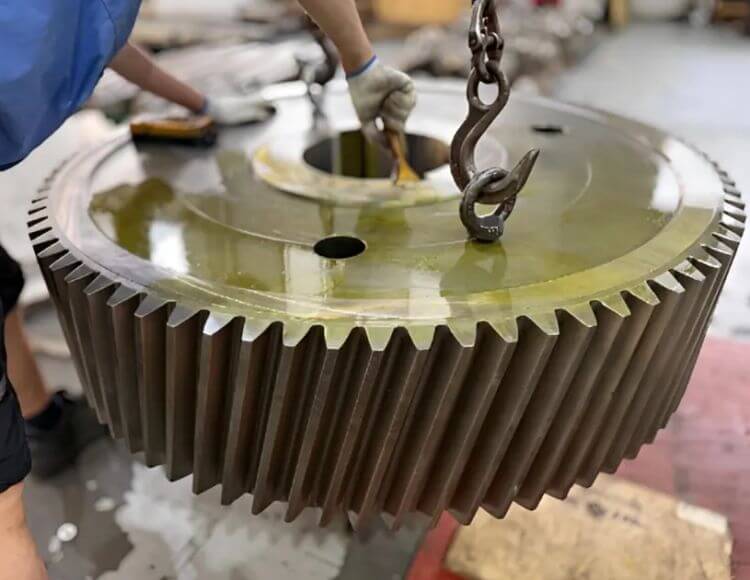
A complete step-by-step guide to the gear manufacturing process.
Step 1: Material Selection
Gear material selection is the first and critical step of gear manufacturing. It directly decides gear load capacity, service life, and machining process. As highlighted by SME Group, the performance of gear steel is a key factor in determining the quality and durability of mechanical parts. Different loads, rotating speeds and working conditions match different gear materials. Below are six most common types:
Carbon Steel
- Representative grades: 45#, S45C
- Features: Low cost, easy cutting, simple heat treatment
- Applicable gears: Light-load, low-speed general equipment gears, ordinary conveyor gears
- Process: Only quenching and tempering, no carburizing quenching and gear grinding
Carburizing Steel
- Representative grades: 20CrMnTi, 20CrNiMo, SCM420
- Features: High surface hardness after tooth surface quenching, good core toughness, and fit carburizing quenching process
- Applicable gears: Heavy-load, impact-resistant, fatigue-resistant and wear-resistant gears for gearbox and reducer
- Process: Pre-quenching and tempering + subsequent carburizing quenching
Quenched & Tempered Steel
- Representative grades: 42CrMo, 40CrNiMo
- Features: High strength after quenching and tempering (higher than carbon steel), good toughness, uniform overall hardness
- Applicable gears: Medium-load, medium-low speed reducer and construction machinery gears
- Process: Only quenching and tempering, no carburizing quenching
Nitriding Steel
- Representative grade: 38CrMoAl
- Features: Small heat treatment deformation, ultra-high precision, high surface hardness
- Applicable gears: High-speed precision gears, machine tool gears, high-precision equipment gears
- Process: Pre-quenching and tempering, followed by low-temperature nitriding, no further tooth surface hardening quenching
Cast Iron
- Types: Grey cast iron, ductile iron
- Features: Good vibration damping, wear-resistant, low cost, easy machining; high brittleness, cannot bear impact load
- Applicable gears: Low-speed, light-load ordinary mechanical gears needing low running noise
Powder Metallurgy Material
- Not traditional rolled steel. Form via metal powder pressing and sintering
- Features: Simple machining (less cutting, no forging), low cost, high material utilization, inner pores store lubricating oil automatically; low overall strength, unable to take heavy impact load
- Applicable gears: Small home appliance gears, miniature motor gears, mass-produced tiny gears
Step 2: Forging Blank
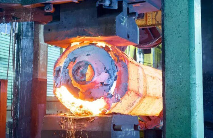
After selecting the proper material (the following content takes commonly-used carburizing steel as the main material), forge the steel bar into a blank close to the gear outer shape. The whole forging process is divided into four steps:
Cutting to length
Cut hot-rolled solid round steel bar (common raw material for carburizing steel, carbon steel, quenched & tempered steel) with a band saw per blank dimension, reserve machining allowance for forging. (Note: Cast iron gear and powder metallurgy gear skip the forging process.)
Heating
Feed cut steel into the heating furnace, heat to the target forging temperature (1150-1250℃ for carburizing steel), and ensure even heat distribution. This step lowers steel hardness for easy forging, improves steel plasticity for smooth plastic forming and avoids cracking under forging strike.
Forming by forging
Core step of forging. Two mainstream methods: closed-die forging and open-die forging
Closed-die forging: For mass-produced standard gears
Form blank via stamping inside a precise closed mould. Blank shape highly matches finished gear blank, smaller allowance and better consistency, becomes mainstream for volume gear production.
Open-die forging: For small-batch, large-size non-standard gears
No fixed mould, forge a rough disc blank directly. Larger allowance leads to more follow-up turning cuts, suit small-batch, large non-standard gears.
Trimming + air cooling
Cut extra flash and burr after forging with a press machine, then place the blank for natural air cooling to room temperature.
Step 3: Normalizing
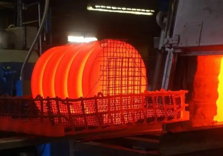
Forged blanks after air cooling have an uneven inner grain structure and massive residual forging stress, so they undergo normalizing treatment. Normalizing splits into three detailed steps:
Furnace loading and heating
Load forged gear blanks neatly into the heat treatment furnace, and slowly heat to normalizing temperature (900℃-950℃ for regular carburizing steel).
Heat preservation
Hold the temperature after reaching the target value. Control holding time by blank thickness to realize uniform temperature from the outer surface to the core and full inner structure transformation.
Discharging and air cooling
Take blanks out after heat preservation completion, and spread blanks for natural cooling in ambient air. (No furnace slow cooling, no water spray cooling; this key difference separates normalizing from annealing.)
Step 4: Rough Turning
The normalized blank has even material and fine cutting properties, start rough turning next. The core goal of rough turning is to remove excess allowance and oxide skin fast, not to pursue precise dimension but reserve sufficient margin for finish turning.
Rough turning cutting trait: Deep tool cutting depth, fast feed rate, low spindle speed, focus on processing efficiency.
Main processing items:
Rough turn two end faces
Level two large end faces of the blank, remove forging irregularities and oxide peeling, control total blank thickness and reserve finish turning allowance on end faces.
Rough turn outer circle
Cut redundant forging allowance and surface oxide layer on outer ring, rough form outer circle contour, reserve 0.8- 2 mm single-side finish allowance on outer circle.
Rough bore inner hole (for gears with hub bore)
Rough drill or rough bore a preliminary inner hole, not reaching the finished hole size, and reserve finish turning allowance for the inner hole.
Rough turn steps
Rough machine hub step contours, cut excess blank stock and reserve finish turning allowance.
Step 5: Ultrasonic Flaw Detection
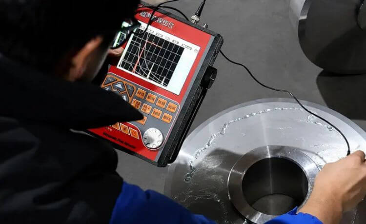
After rough turning removes surface defects, conduct ultrasonic non-destructive flaw detection on the blank to screen hidden inner defects such as cracks and shrinkage cavities.
- Clear burr and dirt on the workpiece detection surface, apply coupling agent.
- Adjust the parameters of the flaw detector and probe, and scan the blank outer circle and end face at constant speed.
- Judge workpiece quality via flaw waveform. Qualified blanks with normal waveform go to the quenching & tempering process; blanks exceeding the defect standard go for rework or scrap directly.
Step 6: Quenching & Tempering
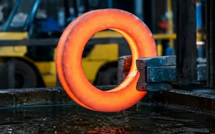
Only flaw-qualified blanks proceed to quenching & tempering. Quenching & tempering contain two core steps: quenching plus high-temperature tempering, which directly decide the final gear strength and hardness.
Quenching
Feed the blank into the heat treatment furnace, heat and hold fully to realize even inner steel structure transformation. Dip the blank into oil quickly after heat preservation to sharply raise base material hardness and strength.
High-temperature tempering
Re-feed the quenched workpiece into the furnace for high-temperature holding, release huge residual stress from quenching, reduce steel brittleness and balance hardness and toughness.
Step 7: Finish Turning
Quenched & tempered blank produces tiny deformation, adopt finish turning to trim the reference shape.
Finish turning cutting trait: Shallow tool cutting depth, small feed rate, high spindle speed, focus on machining precision.
Finish turn two end faces
Correct end face warp from quenching & tempering, strictly control the total gear thickness dimension and keep the two end faces parallel to each other.
Finish turning the outer circle
Remove small residual allowance left by rough turning, precisely control outer circle dimensional tolerance and surface roughness, form outer circle benchmark for follow-up clamping.
Finish the bore inner hole
Machine the inner hole to the drawing-specified size, guaranteeing inner hole roundness and coaxiality as a core positioning benchmark for hobbing and drilling.
Finish turn steps
Precisely machine hub step end faces and step outer circles, making step axial and radial dimensions match the drawing for later assembly positioning.
Step 8: Drilling / Precision Boring
Finish benchmark surfaces via finish turning first, clamp the workpiece against the finished inner hole and end face, and carry out drilling or precision boring. Two main hole types for machining: positioning mounting hole and oil hole.
Positioning the mounting hole
Drill assembly through hole or counterbore on gear end face per drawing position. Direct drill for small-size hole; drill first with allowance, then bore to finished dimension for large-size hole, used for later gear locking and flange fixed assembly.
Oil hole (process on demand)
Drill a lubrication hole for partial reducer gears, run through the hub or gear body to supply lubricating oil during equipment operation.
Step 9: Rough Tooth Cutting
Gear cutting is a core step in the whole gear production. Six common tooth cutting processes below:
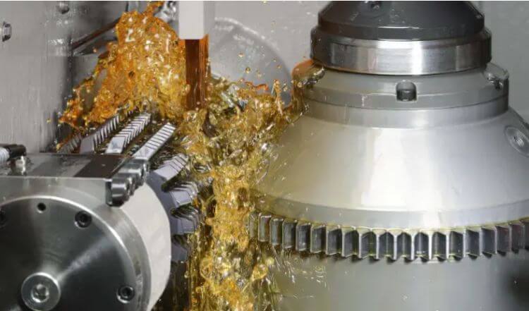
Gear Hobbing
Hobbing belongs to the generating cutting method. Special hob and blank rotate synchronously under a strict transmission ratio to simulate gear meshing. High-speed rotating hob cuts metal with axial feed movement, envelopes the full gear tooth profile through continuous cutting, and forms all gear teeth at one pass. High processing efficiency suits mass outer gear production.
Applicable gear types:
- Spur gear
- Helical gear
- Spline shaft
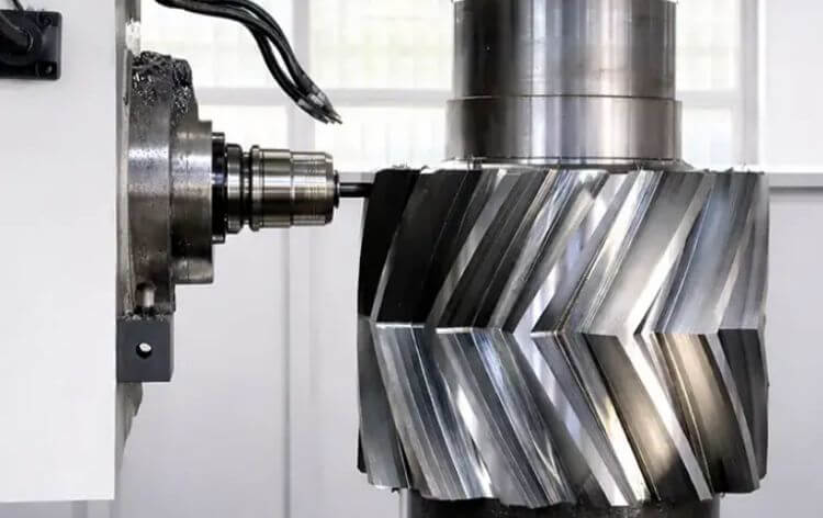
Gear Milling
Milling belongs to the forming cutting method. Use a formed milling cutter with a profile matching the gear tooth slot shape, machine single tooth slot one by one. Rotate the workpiece by a fixed angle after finishing one slot, then machine the next slot, repeat to complete the full teeth. Flexible operation fits small-batch non-standard gear processing.
Applicable gear types:
- Spur gear, helical gear
- Bevel gear
- Non-standard gear
- Large-module, low-tooth-count gear
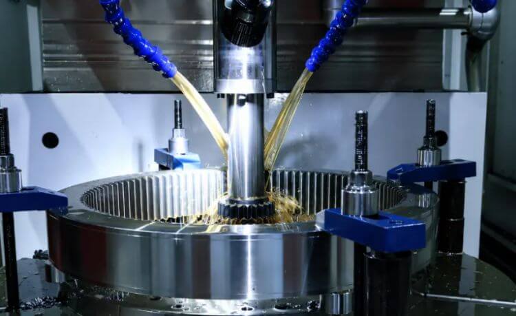
Gear Shaping
Shaper cutter makes reciprocating vertical cutting on the blank, rotating the cutter and workpiece synchronously to cut a standard tooth profile. Processing not affected by workpiece step and structural interference, can machine special structure gears unavailable via hobbing.
Applicable gear types:
- Internal gear (inner ring gear)
- Compound gear
- Step-type outer gear with structural interference
- Double helical gear
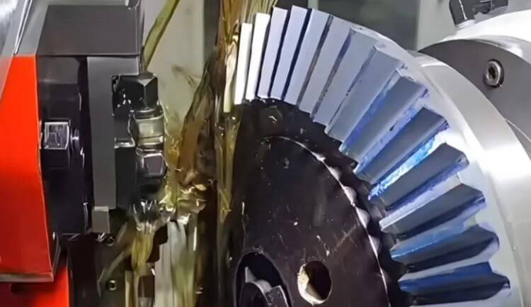
Gear Planing
Planer tool makes linear reciprocating cutting on the blank surface, indexes the workpiece after finishing a single tooth slot, then planes the next tooth, forming a complete tooth gradually. Strong versatility mainly for single-piece and small-batch rough machining of bevel gears.
Applicable gear types:
- Straight bevel gear
- Spiral bevel gear
- Large-module large-size bevel gear
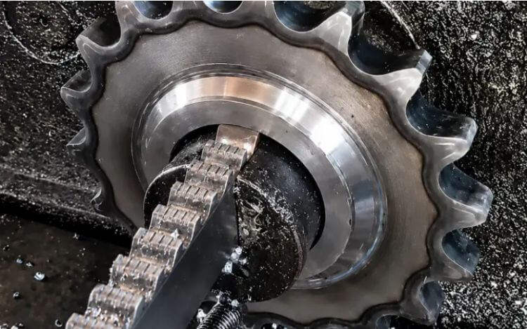
Gear Broaching
An integral formed broach owns a tooth profile matching the gear slot shape. The equipment pulling force pulls the broach through the workpiece once, finishing all gear teeth in a single stroke. Ultra-fast processing speed suits the mass production of small-sized gears.
Applicable gear types:
- All medium-small module straight internal gear
- Inner and outer spline gear
- Standard small cylindrical gear with a simple structure
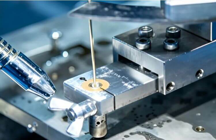
Wire Electrical Discharge Machining (WEDM)
WEDM removes metal via the spark erosion principle. NC equipment controls molybdenum wire moving along a preset gear path to erode redundant stock and form a standard gear contour. No special-formed cutter needed, ultra-high processing flexibility for prototype and small-batch precision processing of special-shaped gears.
Applicable gear types:
- Special-shaped non-standard gear
- Special inner/outer gear blocked by the structure against regular cutter processing
- Special material high-precision miniature gear
Step 10: Heat Treatment
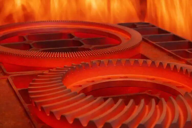
Tooth-cut gear owns complete outer shape but insufficient hardness and poor wear resistance. Change the inner metal structure via heat treatment. Four common heat treatment types: quenching & tempering, induction hardening, carburizing quenching, nitriding.
Quenching & Tempering
Consists of quenching plus high-temperature tempering. No partial gear hardening, upgrade uniform inner and outer gear performance, eliminate inner stress from turning and tooth cutting, and make the gear solid and anti-deformation.
Applicable gear material: Medium carbon steel such as 45 steel, 42CrMo
Applicable transmission scene: Low-speed, light-load regular drive with low demand on wear resistance and precision
Induction Hardening
Surface heat treatment. Only rapidly heat and quench the gear tooth surface, keeping the original core toughness. Hard outer surface for wear resistance, tough inner core for anti-impact. Higher tooth surface wear and compression resistance vs quenching & tempering; shorter production cycle, smaller deformation and better cost performance vs carburizing process.
Applicable gear material: Medium carbon steel such as 45 steel, 42CrMo
Applicable transmission scene: Medium-speed, medium-load general drive
Carburizing Quenching
Core process for heavy-load high-strength gear, especially for low-carbon alloy steel like 20CrMnTi. This steel cannot harden via direct quenching. Add carbon element into gear surface through high-temperature carburizing first, then conduct quenching and tempering.
Applicable gear material: Low-carbon alloy steel such as 20CrMnTi
Applicable transmission scene: Heavy-load drive with frequent start-stop and violent impact load
Nitriding
Low-temperature surface heat treatment. Infuse nitrogen element into the gear surface under low temperature to lift tooth hardness, wear resistance and rust-proof performance. Core advantage: nearly zero heat treatment deformation under full low-temperature processing.
Applicable gear material: Special nitriding steel such as 38CrMoAl
Applicable transmission scene: Small-medium high-speed high-precision low-noise gear drive requiring tiny deformation
Step 11: Finish Machining
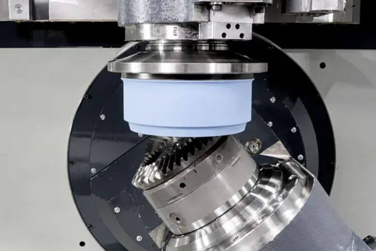
Heat-treated gear gets minor tooth profile and tooth pitch deformation from high-temperature quenching, carries an oxide skin and a decarburized layer on surface, cannot reach the finished precision standard. Correct tooth error and improve surface roughness via finish machining, two mainstream options: gear grinding and gear honing.
Gear Grinding
Grind the tooth surface with a formed or generating grinding wheel, remove the heat treatment allowance little by little to correct the tooth form and lead deviation precisely.
Application: High-precision gear after carburizing, quenching, or nitriding, precision reducer and construction machinery gear
Features: High precision grade, effectively fixes heat treatment deformation, smooth tooth surface, relatively high processing cost
Gear Honing
Honing wheel with teeth rolls with target gear for abrasive grinding, removes tiny burr and surface flaws in meshing rolling to lower gear running noise.
Application: Mass-produced medium-precision gear with small heat treatment deformation, mostly final processing for induction hardened gear
Features: Fast processing speed, lower cost than grinding, small trimming allowance, unable to fix heavy tooth form deformation
Step 12: Surface Treatment
Finished gear after precision machining keeps machining burr and sharp edge on tooth end, inner hole and corner face. Remove burr and chamfer via polishing and barrel finishing.
Deburr & Chamfer
Cut excess flash on the tooth and hole opening, and machine a small round corner on all sharp edges.
Function: Prevent part scratches during assembly, and avoid abnormal tooth wear from falling burr during operation
Application: All specifications for finished gears
Step 13: Magnetic Particle Inspection (MPI)
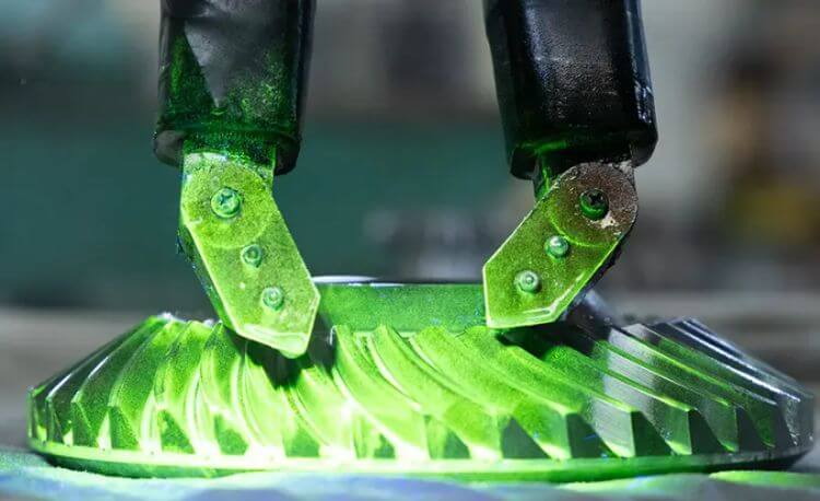
Tiny invisible surface cracks and damage may form on the gear during heat treatment or grinding. These flaws do not change the outer gear shape but drop the structural strength sharply. Complete non-destructive quality test via magnetic particle inspection.
MPI is a common non-destructive test for gear, only fit for ferromagnetic materials such as carbon steel and alloy steel. Principle: Magnetize the gear, then spray magnetic powder. Leakage magnetic field appears at surface defects, including cracks, inclusions and air holes, absorb magnetic powder to form a clear trace for fast intuitive surface quality judgment.
Step 14: Finished Product Inspection
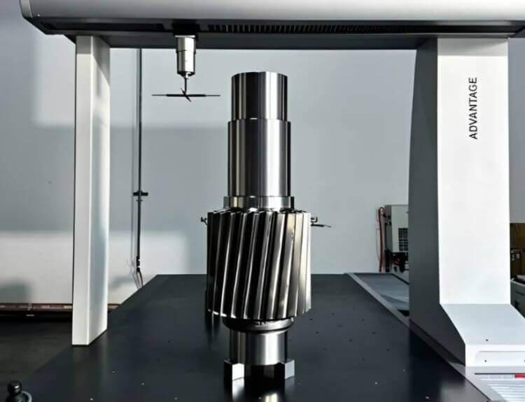
Test gear quality systematically after full machining and surface trimming, split into dimension inspection and precision inspection.
- Dimension inspection: Adopt Coordinate Measuring Machine (CMM) for precise point sampling and full dimension verification of precision gear; use micrometer and caliper to measure key size, including inner hole, common normal length and total thickness for regular mass gear, judge pass status against drawing tolerance.
- Precision inspection: Use a gear runout tester and dedicated gear inspection equipment to test tooth circle runout, tooth form, tooth lead and other meshing precision indexes.
Step 15: Rust Prevention Treatment
Apply anti-rust protection to qualified gear before warehouse storage, using two mainstream processes: black oxide finishing and phosphating.
- Black oxide finishing: Dip the gear into a high-temperature chemical solution to form a compact, thin black film on the surface; the film thickness does not change the original gear dimension precision.
- Phosphating: Forms a crystalline phosphate coating on the workpiece surface, providing better oil storage capacity than a black oxide layer.