
 English
 Español
 العربية
80% of people hold a vague understanding of spline gears. At least 50% of them mistake spline gears for spline shafts. In fact, they are not the same part.
What is a spline gear?
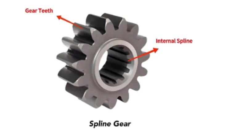
In a broad sense, a spline gear (or splined gear) refers to any gear integrated with spline structures. Most products have internal splines machined on inner holes. A small number of custom special parts adopt external splines on outer circles. This term is only a general industrial name in the industry. It is not an independent gear category under international standards.
In a narrow sense (to distinguish it from spline shafts fitted with external splines), a spline gear refers to a gear-like component with meshing teeth machined onto the outer circumference of the hub and spline grooves machined into the central bore; its function is to transmit torque.
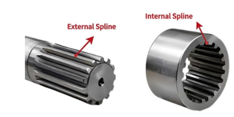
Two types of splines matched with spline gears
External Spline
An external spline consists of continuous protruding tooth profiles machined on outer cylindrical surfaces of shaft parts or special gear blanks. It acts as the male mating component in a spline pair. It is designed to fit into internal spline grooves to form a complete synchronous transmission structure. Besides, it supports fixed assembly and axial sliding assembly. It acts as the core structure of gearbox shifting mechanisms.
Common processing methods:
- External spline hobbing: Use special spline hobs to continuously cut the workpiece outer circles. Cut all external spline tooth profiles in one pass. This mainstream mass production process delivers stable machining consistency.
- CNC milling: Adopt numerical control programs to control form cutters for indexing milling. Fit small-batch production and non-standard external splines of special specifications.
Internal Spline
An internal spline refers to a ring of evenly distributed spline grooves machined on the inner holes of hubs on a gear or other mechanical parts. It serves as the female mating component in a spline pair. It can transmit torque in fixed or sliding mode. This structure forms an integrated unit with gears. It features high overall rigidity, stable operation and high concentricity precision. It is widely used in reducer hub gears and similar components.
Common processing methods:
- Internal spline shaping: Shaping cutters perform a reciprocating shaping motion. Remove the inner hole material layer by layer to machine spline grooves step by step. This flexible process can produce internal splines with large modules and irregular, non-standard profiles, meeting customized manufacturing requirements.
- Internal spline broaching: Use an integrated broach for one straight feed stroke. Finish a full set of internal splines in a single pass. It boasts high mass production efficiency. It ranks as the top choice for mass production of standard internal splines with stable tolerances and high overall cost performance.
How do spline gears work?
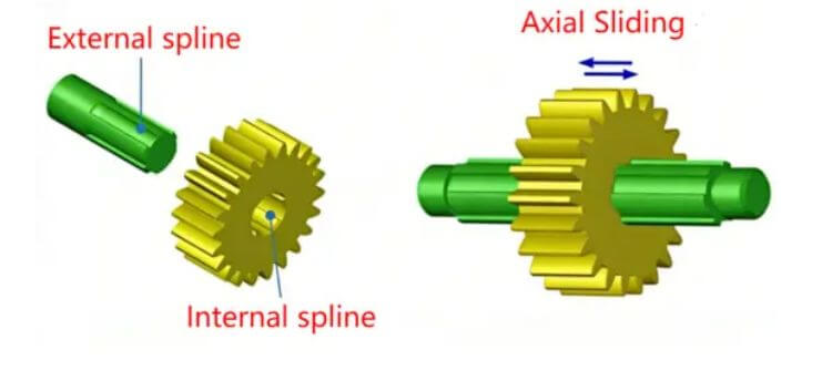
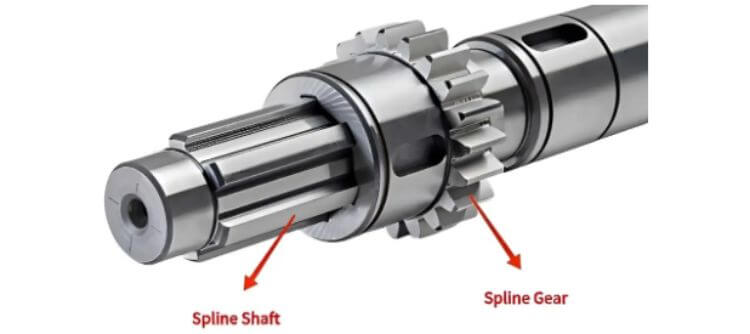
Spline gears work under two modes: fixed transmission and sliding transmission. Under either mode, a spline gear must be assembled with a transmission shaft fitted with external splines (spline shaft). They form a complete spline pair to realize power transmission.
Complete working process:
- Assembly: Fit external spline shafts into inner spline hub holes at spline gear centers. Select two matching modes per working condition for precise engagement of internal and external splines.
Fixed assembly: Very small fit clearance between internal and external splines. The spline gear fastens tightly on the spline shaft. The two parts rotate fully synchronously with no relative sliding.
Sliding assembly: Reserve reasonable fit clearance between internal and external splines. The spline gear rotates synchronously with the shaft. Meanwhile, it slides freely along the axis of the spline shaft. - Spline shaft rotation: The power source drives the spline shaft, causing the external splines on the shaft’s outer surface to rotate synchronously.
- Torque transmission: Protruding teeth on the spline shaft push against internal spline grooves inside spline gear holes during rotation. Multiple sets of spline teeth share the load evenly. Then transfer rotary torque from the spline shaft to the spline gears smoothly.
- Precise centering: The evenly distributed spline teeth engage and constrain one another, ensuring high coaxiality between the spline gear and the shaft; this minimizes vibration and runout during high-speed operation, resulting in smoother, quieter power transmission.
Advantages and Disadvantages of Using Spline Gears
Advantages
- Higher torque capacity with even load sharing
Multiple rows of spline teeth around the gear’s inner bore engage and bear loads at the same time. Unlike flat keys that bear force at a single point, spline teeth spread torque evenly and stop stress concentration from forming.
- Superior coaxiality, smooth and quiet operation
Internal and external splines fit all the way around the circumference. Their centering accuracy outperforms single-key connections by a large margin. The unit runs with minimal vibration and noise at high RPM and maintains steady transmission precision over long service hours.
- Two usable transmission forms: fixed and sliding
Adjust the fit clearance between internal and external splines to get two working modes. One is a rigid, fixed drive with zero relative sliding. The other lets the gear slide along the shaft’s axis while spinning synchronously. Standard flat-key gears cannot deliver this sliding function.
- Robust construction for extended service life
Internal splines are machined as one piece with the gear hub. The finished part has high overall strength and strong resistance to deformation. It holds up far better under continuous heavy loads over long periods.
- Wide compatibility across industrial applications
Spline gears support three common centering methods: major diameter centering, minor diameter centering and tooth flank centering. They meet varying precision and load requirements for different machinery and fit most industrial working conditions.
Disadvantages
- Complex machining steps lead to higher production costs
Machining internal splines calls for dedicated equipment such as broaching machines and gear shapers, plus custom cutting tools. The whole process involves many steps and longer lead times. Even mass production runs carry a higher per-unit cost compared to standard flat-key gears.
- Strict assembly tolerance and demanding maintenance rules
Spline teeth must align perfectly before meshing. Forced fitting scratches tooth surfaces and renders the whole part unusable. Spline gears only match designated spline shafts, which limits interchangeability. Replacement costs after wear also run higher than standard flat-key assemblies.
- Strict lubrication requirements
Sliding splines generate constant back-and-forth friction between tooth surfaces during operation. Operators must replenish grease or oil on a regular schedule. Poor lubrication causes scoring and seizure on tooth flanks, which breaks down the entire transmission system.
- Restrictions on compact lightweight design
The gear hub needs sufficient wall thickness to machine full internal spline grooves. Ultra-thin, lightweight designs are not feasible here, so these gears do not suit tiny precision machinery with severely limited installation space.
Common comparisons for spline gears
Spline Gear vs Spline Shaft
Different basic structures
- Spline gear: Disc-shaped gear base, composed of outer transmission meshing teeth + internal splines on the inner hole.
- Spline shaft: Long shaft base, composed of protruding external splines on the outer circle + smooth shaft sections.
Different core functions
- Spline gear: Driven part. It receives torque transmitted from the spline shaft and outputs power through outer gear meshing. Besides, it reserves a reasonable fit clearance to realize axial sliding while rotating synchronously.
- Spline shaft: Driving part. It connects motors or engines and outputs torque outward as a power input carrier.
Different machining processes
- Spline gear: Forged gear blank as raw material. Internal hole splines adopt broaching, shaping and internal grinding. Limited inner machining space brings higher processing difficulty.
- Spline shaft: Round steel bar as raw material. External splines adopt hobbing, milling, external grinding and cold rolling. Sufficient outer machining space delivers high mass production efficiency.
Different force-bearing features
- Spline gear: Two force bearing positions. Internal hole splines bear input torque. Outer gear teeth bear output loads.
- Spline shaft: Only external spline teeth bear torque. The whole shaft bears combined bending and torsional stress.
Different failure forms
- Spline gear: Common failures include internal spline groove wear, tooth surface pitting corrosion, outer gear tooth breakage and hub deformation.
- Spline shaft: Common failures include external spline tooth wear, cold rolling tooth collapse, shaft torsional deformation and fracture at the spline root.
Different rigidity and dimensions
- Spline gear: Hub thickness decides internal spline depth. Ultra-thin structures are unavailable. Disc shape brings good rigidity with low deformation risk.
- Spline shaft: Wide length range. Long shafts carry weak rigidity and vibrate easily at high speeds. A thin, lightweight shaft body can be manufactured.
Different application scenarios
- Spline gear: Gearbox shift gears, reducer hub gears, inner gear hubs of planet carriers.
- Spline shaft: Gearbox input and output shafts, construction machinery transmission shafts, walking drive shafts of agricultural machinery.
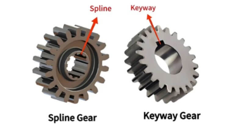
Spline Gear vs Keyway Gear
Different internal connection structures
- Spline gear: Full ring of internal splines machined on the hub inner hole. It transmits power via multi-tooth engagement.
- Keyway gear: Only one or two key slots on the inner hole. It bears force through one flat key.
Different torque load capacities
- Spline gear: Multiple spline teeth share loads simultaneously. It bears large torque and resists heavy loads and impacts.
- Keyway gear: Single flat key undertakes full torque. Stress concentration occurs easily. It only fits medium and light loads. Keys break easily under impact.
Different centering precision
- Spline gear: Precise full-circle engagement brings high coaxiality. Low vibration and noise at high speeds.
- Keyway gear: Centering relies on clearance between the shaft and the hole. Poor alignment with obvious runout at high speeds.
Different transmission modes
- Spline gear: Adjust the fit clearance between internal and external splines to realize fixed transmission and sliding transmission.
- Keyway gear: Flat keys embed tightly inside key slots with no sliding space. It only supports fixed transmission.
Different machining difficulty
- Spline gear: Special equipment and cutters for broaching or shaping are required. More working procedures and higher manufacturing costs.
- Keyway gear: Ordinary key slotting and milling equipment suffice. Mature, simple procedures, fast production speed and low cost.
Different maintenance costs
- Spline gear: Matched with spline shafts. Once spline teeth wear, operators replace the whole gear or even supporting spline shafts with high maintenance costs.
- Keyway gear: Flat keys are a general standard part. Operators only replace worn flat keys instead of whole gears for low maintenance costs.
Different application scenarios
- Spline gear: Automobile gearboxes, construction machinery reducers, agricultural machinery speed change mechanisms, heavy-duty servo reducers.
- Keyway gear: Small conveyors, light machine tools, ordinary small reduction equipment, simple transmission devices without speed change function.
Spline vs Gear
Different core functions
- Spline: Only transfers torque synchronously between shafts and hubs. It does not change the rotating speed, torque magnitude, or power transmission direction.
- Gear: Transmits power through tooth meshing. It changes the rotating speed, adjusts the torque and switches the power transmission direction.
Different matching rules
- Spline: Only internal splines match external splines. The two parts carry identical module and tooth numbers. They rotate at the same speed.
- Gear: Matches and meshes with other gears. Mating gears carry different tooth counts and different rotating speeds. Driving gears drive driven gears to realize speed and torque conversion.
Different design positioning
- Spline: Shaft-hub connection structure. It solves coaxial assembly and the synchronous rotation of parts.
- Gear: Speed change transmission component. It undertakes power conversion and speed regulation.