
 English
 Español
 العربية
A detailed selection guide for reduction gears, covering types and key considerations.
What are reduction gears?
Reduction gears are a structured assembly of meshing gears. Their core function is to change the output state of rotational power through gear ratio differences: reducing input speed and increasing output torque proportionally. They are the core internal components widely used in gear reducers and industrial gearing.
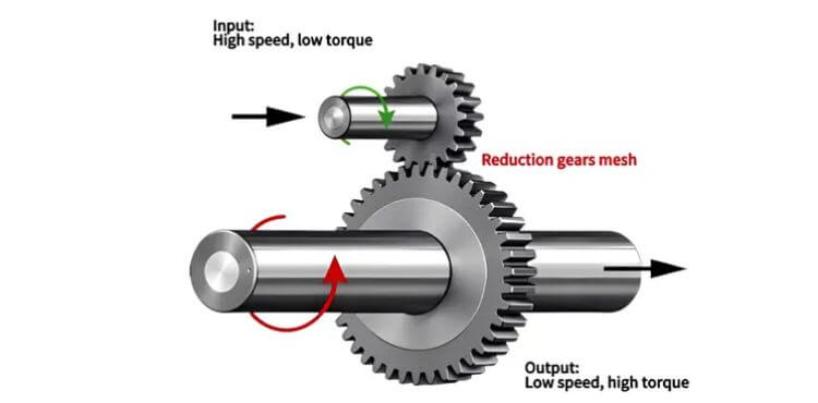
How to select reduction gears?
Common types of reduction gears include spur, helical, bevel, planetary, and worm-wheel reduction gears. Each gear type features distinct mechanical characteristics and application boundaries.
Spur reduction gears
- Why you should select them:
Spur reduction gears are your ideal choice for parallel-shaft speed reduction with a limited budget. Featuring a simple structure, they bring low-cost manufacturing, inspection and replacement. They work well for low-speed auxiliary mechanisms where cost control is critical. - Drawbacks you have to accept:
The teeth of the spur reduction gears engage fully at the same time, bringing significant meshing impact and noticeable noise. Their load-bearing capacity is limited, making them unsuitable for continuous heavy-load operating conditions. - When you shouldn’t select them:
Do not select spur reduction gears for high-speed, continuously operating equipment, noise-sensitive machinery, or high-torque main drive chains.
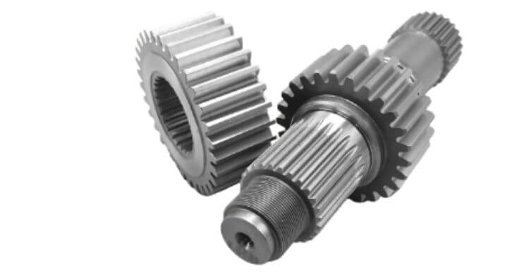
Helical reduction gears
- Why you should select them:
Helical reduction gears overcome the drawbacks of spur gears: high noise and insufficient strength. Their gradual tooth engagement enables quiet, smooth (shock-free) power transmission. They can handle heavy-duty and 24-hour non-stop parallel-shaft transmission conditions, making them hold a dominant position in general industrial power transmission. - Drawbacks you have to accept:
The helix angle of helical reduction gears generates axial thrust. Bearings with sufficient load-bearing capacity must be installed to counteract this axial force; otherwise, premature wear will occur. Their manufacturing costs are higher than those of spur reduction gears. - When you shouldn’t select them:
Do not select helical reduction gears for simple, low-speed, and low-cost auxiliary devices. If spur reduction gears meet the requirements, the use of helical reduction gears should be avoided to prevent over-specification.
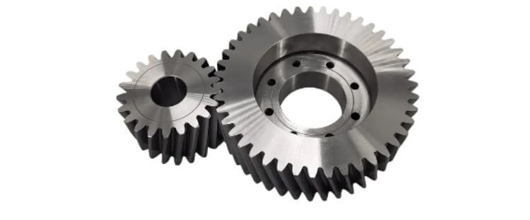
Bevel reduction gears
- Why you should select them:
All other reduction gears work on parallel or offset shafts. When it is necessary to change the direction of power transmission (typically by 90 degrees) while reducing rotational speed, the bevel reduction gears will be the preferred choice. - Drawbacks you have to accept:
They require high precision in installation and alignment. Both axial and radial forces are generated during operation, which places higher requirements on bearing layout. Though spiral bevel gears deliver better performance, they come at a higher cost. - When you shouldn’t select them:
Do not select bevel reduction gears if your input and output shafts can be arranged in parallel. Parallel-shaft helical sets will provide better efficiency and lower assembly risk.
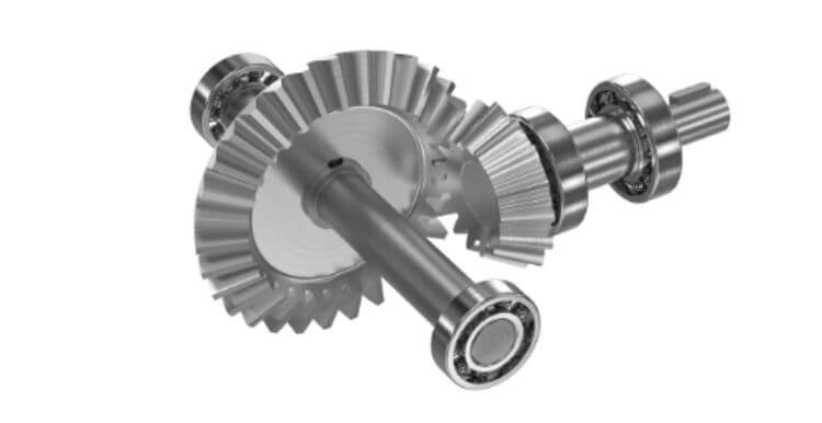
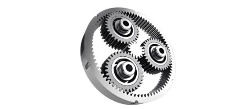
Planetary reduction gears
- Why you should select them:
Planetary reduction gears solve the common conflict between high torque requirements and limited installation space. Multiple planet gears share the load simultaneously to achieve high torque density within a compact footprint. Furthermore, they offer excellent rotational accuracy, making them ideal for servo-driven motion control applications. - Drawbacks you have to accept:
More components of the planetary reduction gears mean complex assembly and extremely high requirements for part precision. Maintenance is difficult, and component costs are relatively high. Improper assembly will greatly shorten service life. - When you shouldn’t select them:
Do not select planetary reduction gears for low-cost, low-precision general transmission projects. If installation space is sufficient and cost is strictly constrained, parallel-shaft helical gears may be a more practical alternative.
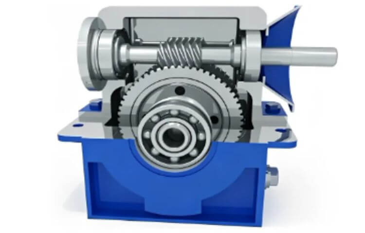
Worm-wheel reduction gears
- Why you should select them:
Worm-wheel reduction gears achieve an extremely high single-stage reduction ratio without multi-stage stacking. Under an appropriate worm lead angle, they provide inherent self-locking to prevent load reverse movement or back-driving, which is highly valuable for lifting and holding mechanisms. - Drawbacks you have to accept:
The sliding friction between tooth surfaces generates substantial heat and leads to reduced efficiency. They are not suitable for continuous, uninterrupted operation. Compared with rolling-contact gear pairs, they exhibit higher wear rates. - When you shouldn’t select them:
Do not select worm-wheel reduction gears for main transmission systems requiring long-duration continuous operation. If high efficiency is your top priority, other gear types should be preferred.
5 considerations for your selection
Selecting reduction gears properly directly determines overall equipment performance and cost. Below are five considerations you must consider during selection.
Shaft Layout Constraints
Shaft arrangement is the first and decisive screening factor. Different reduction gears are mechanically designed for specific shaft relationships and cannot be substituted arbitrarily.
Spur and helical reduction gears apply only to parallel shafts. Bevel reduction gears are exclusively used for intersecting and right-angle power transmission. Worm-wheel reduction gears are designed for offset and non-intersecting shaft structures.
A mismatch in shaft arrangement renders the selected gear type structurally unworkable.
Actual Working Conditions
Nominal torque and speed parameters are not sufficient for final selection. Engineers must evaluate real operating cycles.
Continuous heavy-duty operation favors helical or planetary reduction gears, while intermittent low-duty scenarios can adopt more cost-effective spur or worm-wheel solutions. Worm-wheel reduction gears are not suitable for long-term continuous operation due to heat generated by sliding friction, and spur reduction gears cannot withstand frequent shock loads.
Matching gear characteristics to actual operating conditions effectively prevents premature wear and failure.
Space-Torque Balance
Space limitation is one of the most common contradictions in mechanical design.
When high output torque is required within a compact installation space, planetary reduction gears are the optimal choice due to their multi-load-sharing structure and high torque density.
If installation space is sufficient, conventional parallel-shaft helical reduction gears provide better cost‑performance and easier maintenance.
Side-forces and Bearing Matching
Different gear types produce different additional forces during meshing, which directly affect bearing life and equipment stability.
Helical reduction gears generate axial thrust, while bevel reduction gears produce both axial and radial forces. These side forces must be counteracted by matched bearing layouts.
Neglecting force characteristics will cause abnormal noise, vibration and accelerated component damage.
Cost-Performance Balance
The best gear solution is not the highest-grade one, but the most suitable one.
High-precision planetary reduction gears or spiral bevel reduction gears deliver excellent performance but come with much higher manufacturing and maintenance costs. For ordinary low-speed, low-precision auxiliary mechanisms, standard spur or helical reduction gears fully meet operational requirements.
Reasonable selection avoids unnecessary costs while maintaining stable mechanical performance.